The band-pass filter is a too broad concept, narrow-band broadband, LC/microstrip/coaxial/waveguide/medium. Various patterns of resonators, various patterns of coupling structure. However, no matter how changes are made, there are two concepts that cannot be avoided at all times; resonance and coupling, and various design methods are all for how to accurately determine the coupling frequency between the resonant frequency and the resonator. Various technological advances are also aimed at finding smaller, higher-Q resonant structures.
At the same time why do you like the filter so much, the filter is a basic device of the microwave, in the previous paper has proved that any broadband matching network is a filter structure, its own feeling of the microwave also benefit from this device .
· A waveguide coaxial conversion is a filter structure
A polarization converter is a filter structure
An OMT is a filter structure
· A splitter can also be a filter structure
· Even one antenna is a filter structure (to achieve a matching of 50 ohms and free space impedance)
· You can also combine filters and attenuators to design an equalizer
When through a lot of practice, with the concept of a large number of different structures of resonant structures and coupled structures, we can feel that in the microwave active product design, the signal may fluctuate from those places, you can make your link More clean and orderly. In the future, we plan to summarize valuable filter design concepts. Today we use a 5th-order 1805MHz to 1880MHz coaxial comb filter example to illustrate how to design a simple bandpass filter.
1. Bandpass filter design steps
A bandpass filter should follow the following design steps:
1.1) Analysis of indicators, preliminary planning of the program: how many levels of resonance, how much Q is appropriate, what kind of structure. These can be performed by couple-fil, and physical characteristics such as power capacity/temperature characteristics/Q values that can be achieved in the form of structures need to be judged based on experience. In general, the Q value is:
· Microstrip/LC: Approximately 50 to 200 orders of magnitude
Suspended Stripline/Spiral Filter/TEM Media: Approx. 200 to 800 levels
· Coaxial combing line: 800 to 2000 levels
· Bird: About 6000
· TE01 medium: around 1000~20000
1.2) Structural Planning: Structural planning is a very important step in product design. You can determine how the resonators are arranged through the structural plan and what coupling methods are appropriate for them, and specify the direction for subsequent designs.
1.3) Simulation
1.4) Drawing
This article mainly describes how to perform a quick simulation design.
2 filter simulation steps
There are many softwares that can directly calculate the initial value of the filter structure size (ansoft designer/ADS/genersys/uwave, etc.). This article describes how to determine the size of the structure step by step.
2.1) Intrinsic Mode Determines Individual Resonator Size
Before computing the eigenmode, we can roughly estimate the resonator length by calculating the wavelength of the transmission line, but in many cases the product size is limited and the resonator design can only be performed within the limits.
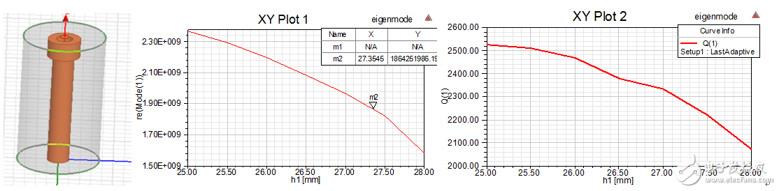
Fig.1 Simulation results of eigenmode frequency and Q value
2.2) Determine input coupling tap position
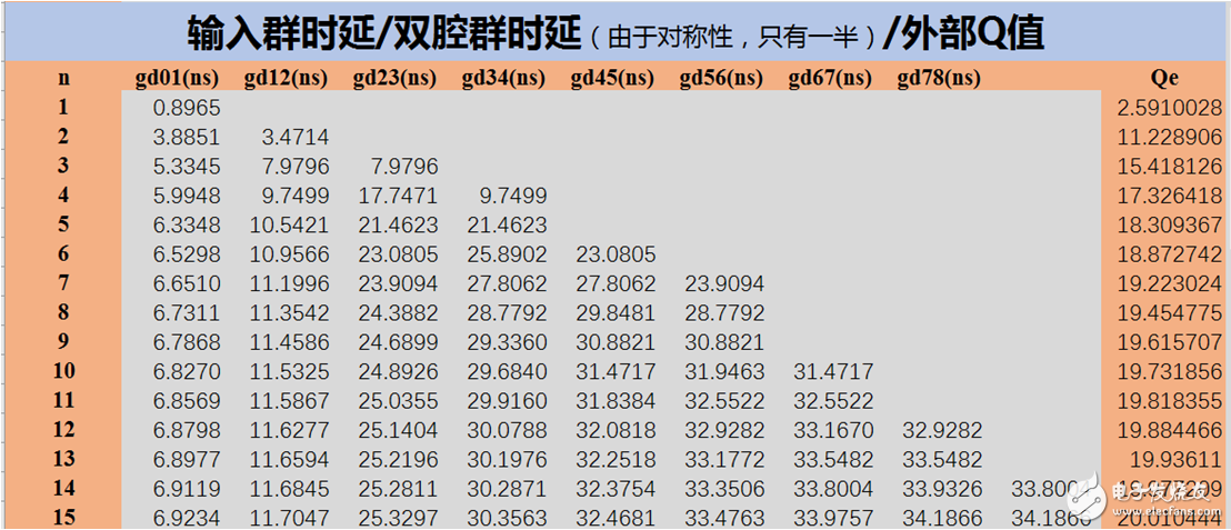
Fig. 2 Ideal design parameters of 5th order 1840MHz BW80M filter
There are two ways to determine the input coupling: one kind of echo group delay method, one kind of external Q value method (using the PML port plus eigenmode to simulate the Q value) This article uses the group delay method to determine the input coupling, and the model and result are shown in the figure. 3 (the second resonator is detuned or not drawn), tap position is approximately 5.5mm.
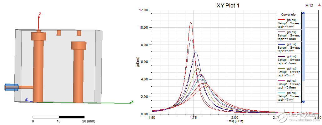
Figure 3 Input-coupled simulation
3.3) Determine the coupling size between stages
There are two ways to determine the coupling between stages, coupling coefficient method and group delay method. The coupling coefficient method uses two eigenmodes of the double resonator to simulate two modes. The coupling coefficient is calculated by (f12-f22)/(f12+f22). . This paper uses group delay method. Looking at the table in Fig. 2, it is known that the 12-coupled group delay requires 10.5 ns and the 23-coupled group delay needs 21 ns.
Inter-stage coupling can be changed in many ways. It can be achieved by adjusting the distance between two resonators. It can be realized by adding ridges or windows at fixed intervals. Here, it is achieved by changing the distance between the resonators for convenience. The second resonator height is adjusted to the same height as the first resonator. The appropriate coupling parameters are found by scanning the distance between the two resonators.
The results of the model and the first scan are shown in Fig. 4. The first scan revealed that the two frequencies are not aligned (the group delay pattern is misaligned). This is because the input coupling has a pull on the first-order resonant frequency. Select a pitch such as LS1=14mm and fine-tune the height of the resonator 2 so that the group delay pattern is symmetrical. The scan results are shown in Figure 5.
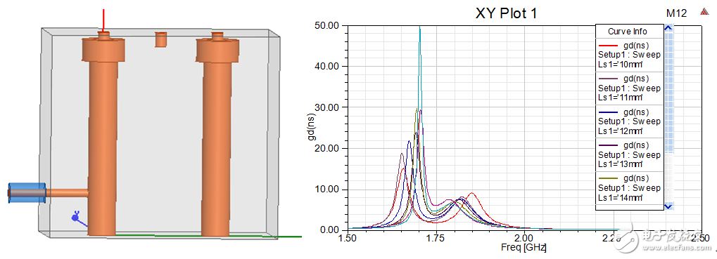
Figure 4 Interstage coupling first scan
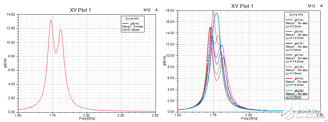
Figure 5 Interstage coupling second scan
Through the second scan, it can be seen that the height of resonator 2 is 27.3mm, the distance between 12 resonators is 14.5mm, and the distance between 23 resonators is slightly larger than 16, and 16.5mm is used here. The scanning range can be widened to obtain more accurate values.
2.4) Preliminary simulation of the overall filter model
Having obtained the resonator dimensions and coupling dimensions through the previous steps, it is now possible to bring these dimensions into the model for overall filter simulation. The model and preliminary results are shown in Figure 6. It can be seen that basically the shape of the filter has come out and the standing wave is slightly worse.
This is because adding the 12 and 23 couplings has a frequency drag on the resonators 2 and 3, and the resonator size in the middle of the filter is basically the same. Here we make a fine scan of h3=h2 and the result should be better. See results once.
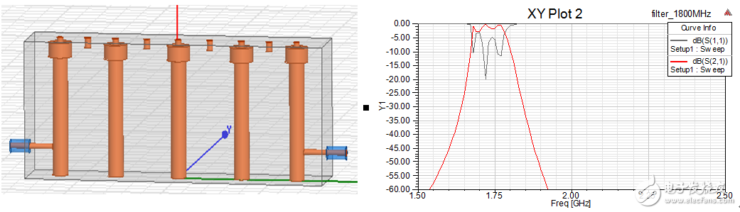
Figure 6 Filter preliminary simulation results
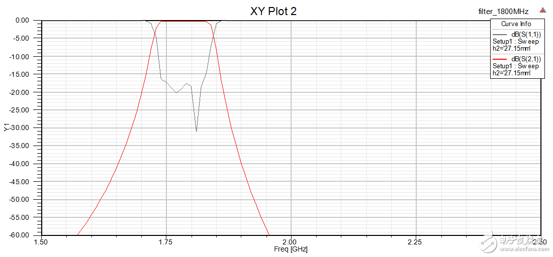
Fig. 7 Results after scanning the height of h2 slightly
In fact, there is a large range of tuning devices for the filter of the cavity type. At this stage, it is basically unnecessary to optimize the model very finely, and it is possible to process the drawing directly. Slightly reduce the height of some resonators when drawing out, to avoid the low frequency of the processed products can not be debugged.
All other types of filters can be precisely designed through such steps.
 Inquiry Basket ( 0 )